 en
en  русский
 Español
OH1 Horizontal Magnetic Drive Pump
Cat:Magnetic Pump
Performance Range: · Diameter: DN25~DN400 · Flow Rate: Up to 2000 m³/h · Head: Up to 250 m · Power: Up to 560 ...
See DetailsContent
Axial flow pumps occupy a specific and critically important niche in fluid handling engineering — they are the preferred choice wherever very high flow rates must be moved against relatively low heads, and where the physical configuration of the installation site places demands on the pump's orientation, footprint, and submergence characteristics. The two principal configurations of axial flow pumps — horizontal and vertical — share the same fundamental hydraulic operating principle but differ substantially in their mechanical layout, installation requirements, performance characteristics at specific duty points, and suitability for different application environments. Choosing between horizontal and vertical axial flow pumps without a clear understanding of these differences frequently results in pumping systems that are mechanically sound but operationally compromised — either producing insufficient flow, consuming excessive energy, requiring impractical civil works, or demanding maintenance access that the installation does not provide. This article examines both configurations in the technical detail needed to make an informed selection decision.
Before examining the differences between horizontal and vertical configurations, it is essential to understand the hydraulic principle common to both. An axial flow pump — also called a propeller pump — moves fluid using an impeller designed as a set of angled blades arranged around a central hub, similar in concept to a ship's propeller. As the impeller rotates, the blade angle imparts momentum to the fluid in the axial direction — parallel to the pump shaft — rather than in the radial direction as in centrifugal pumps. This axial momentum transfer moves large volumes of fluid with relatively little pressure increase per stage, which is why axial flow pumps are characterized by very high specific speed values (Ns typically 8,000 to 20,000 in US customary units, or 150 to 400 in SI units), very high flow rates, and low developed head compared to centrifugal or mixed-flow designs.
The impeller in an axial flow pump is followed by guide vanes (diffuser vanes) that remove the swirl component imparted to the fluid by the rotating blades and convert remaining rotational kinetic energy into additional pressure recovery. The efficiency of an axial flow pump is highly sensitive to the match between the operating point and the design point — axial flow pumps have steep, unstable head-flow curves at low flow rates and can exhibit operational instability including surge, vibration, and blade stall if operated significantly below their design flow. This characteristic means that accurate system resistance calculation and operating point matching is more critical for axial flow pump selection than for centrifugal pump applications, where the flatter head-flow curve provides more tolerance for operating point variation.
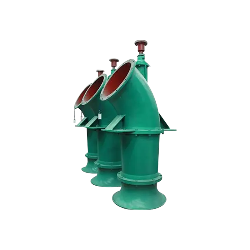
Vertical axial flow pumps are the dominant configuration in large-scale water management, irrigation, drainage, flood control, and industrial cooling applications. In this configuration, the pump shaft is oriented vertically, the impeller assembly is submerged in the pumped liquid, and the motor is mounted above the water surface level — either directly coupled to the pump shaft at the top of the column, or connected through a right-angle gearbox where motor orientation or speed requirements dictate. The pumped fluid enters the impeller from below in the axial direction and is discharged upward through the pump column to the surface outlet.
A vertical axial flow pump installation consists of several distinct mechanical sections assembled vertically. The pump bowl assembly at the bottom contains the impeller, guide vanes, and bowl casing — this is the hydraulic heart of the pump that does the actual fluid work. The column pipe section extends from the bowl assembly to the surface, carrying the pumped fluid upward and housing the lineshaft that connects the submerged impeller to the surface-mounted motor. At the surface, the discharge head assembly provides the structural mounting for the motor, the bearing housing for the top of the lineshaft, and the transition to the horizontal discharge piping. The lineshaft runs inside the column through a series of intermediate lineshaft bearings that are spaced at regular intervals — typically every 1.5 to 3 meters — to prevent shaft whip and maintain concentricity. These intermediate bearings are lubricated either by the pumped fluid passing upward through the column, or by a separate water or oil lubrication system depending on the pumped fluid characteristics.
The vertical configuration provides several significant advantages over horizontal layouts for many high-volume, low-head pumping applications. The motor and all electrical equipment remain above the water surface, protected from flooding — a critical safety and operational advantage in flood control and drainage pumping stations where the pump must continue operating during rising water levels that could submerge a horizontal motor installation. The submerged pump bowl requires no priming since it is permanently immersed in the source water, eliminating the priming infrastructure and operational procedures required for horizontal installations where the pump is mounted above the water source. The vertical configuration also minimizes the wet well footprint per pump — only the pump bell mouth diameter occupies the wet well plan area at the pump level, whereas a horizontal pump would require its full length and access clearance to be accommodated within the wet structure.
Horizontal axial flow pumps orient the pump shaft horizontally, with the motor mounted alongside or coaxially at one end and the impeller within a horizontal casing that connects to the suction and discharge piping in a straight-through or elbow arrangement. This configuration is physically more compact in the vertical dimension — the entire pump assembly occupies only the height of the casing and motor rather than requiring depth sufficient for a submerged bowl and column — making it the preferred choice where installation depth is limited, where the pump must be mounted at or above the operating water surface, or where maintenance access from the side or top of the pump is preferable to working on equipment distributed vertically through a pump column.
In a horizontal axial flow pump, the fluid enters the impeller through an inlet bell or suction elbow oriented to deliver flow axially into the rotating blades, passes through the impeller and guide vane assembly, and exits through the discharge casing into horizontal outlet piping. The shaft sealing arrangement at the point where the shaft exits the pump casing to connect to the motor or coupling is a critical design area — horizontal axial flow pumps for clean water may use mechanical seals or packed glands, while those handling abrasive, chemical, or process fluids require more specialized sealing arrangements including double mechanical seals with barrier fluid systems. Unlike vertical configurations where intermediate lineshaft bearings are required for long column installations, horizontal axial flow pumps use only the bearings at each end of the relatively short shaft, simplifying the bearing system and reducing the number of lubrication points requiring maintenance.
Horizontal axial flow pumps are particularly well suited to applications where the available civil structure depth is limited — such as water intake facilities built into existing embankments, tidal barrages, or canal flow diversion structures where the water level may be at or near ground level. In industrial process applications involving corrosive, viscous, or solid-laden fluids, the horizontal configuration allows easier access to the mechanical seal, bearings, and impeller for inspection and replacement without requiring the disassembly of a vertical column structure. Horizontal axial flow pumps are also preferred for mobile or temporary pumping applications — dewatering of construction sites, temporary irrigation systems, and emergency flood response — where the pump must be rapidly deployed, positioned, and recovered without the civil infrastructure that a permanent vertical pump installation requires.
While both configurations share the same hydraulic principle, their practical performance characteristics differ in ways that are directly relevant to application suitability and system design. The following table summarizes the most important comparative parameters.
| Parameter | Vertical Axial Flow Pump | Horizontal Axial Flow Pump |
| Typical Flow Range | 500 – 100,000+ m³/h | 100 – 50,000 m³/h |
| Typical Head Range | 2 – 20 m | 1 – 15 m |
| Installation Depth Required | High (column + bowl) | Low (shallow sump acceptable) |
| Motor Flood Risk | Low (motor above water) | Higher (motor at operating level) |
| Priming Required | No (self-priming by submergence) | Yes (if mounted above water) |
| Wet Well Footprint | Small (only bell mouth diameter) | Larger (full pump length + clearance) |
| Impeller Access for Maintenance | Requires column removal or pump withdrawal | Direct access from end of casing |
| Bearing System Complexity | Higher (multiple lineshaft bearings) | Lower (end bearings only) |
| Suitable for Variable Water Level | Excellent | Limited (requires stable intake level) |
The civil and structural requirements of horizontal versus vertical axial flow pump installations frequently determine the configuration choice before hydraulic performance considerations are even evaluated — particularly in retrofit or upgrade projects where existing civil works constrain what can be installed. Understanding these civil requirements in detail is therefore an essential part of any axial flow pump selection process.
Vertical axial flow pump installations require a wet well or sump of sufficient depth to accommodate the pump bowl assembly at the required submergence below minimum operating water level, plus the full column length from bowl to surface, plus adequate clearance below the bowl for unobstructed inflow. The minimum submergence requirement — the depth of liquid above the impeller center needed to prevent vortexing and air entrainment — is typically 1 to 2 times the pump inlet diameter for open sump installations and must be maintained throughout the operating range of water levels. Where variable water levels are anticipated, the column length may need to be designed to maintain adequate submergence at minimum water level while keeping the motor clear of the maximum flood level at the top of the installation — a constraint that can result in very long column assemblies for sites with large operating water level ranges.
Horizontal axial flow pump installations require much less depth — the pump casing need only be positioned to maintain positive suction head at the impeller centerline, which for a pump installed at or near water level can be achieved with a shallow intake structure or a short suction elbow. However, horizontal installations require more plan area, more structural support for the horizontal casing and motor assembly, and — in applications where the pump is mounted above the water surface — priming systems and potentially foot valves or vacuum-assisted start arrangements to establish initial prime before startup. These additional systems add capital cost and operational complexity that the self-priming characteristic of a submerged vertical installation avoids.
Both vertical and horizontal axial flow pumps are available with either fixed-pitch or adjustable-pitch impellers, and this capability significantly affects the pump's operational flexibility — a particularly important consideration given the steep, narrow operating range of axial flow pumps on a fixed-pitch, fixed-speed configuration.
Fixed-pitch axial flow pumps offer maximum efficiency only at the design operating point, with efficiency falling rapidly as flow or head deviates from design conditions. In installations where the system head is relatively constant and the required flow rate is stable, fixed-pitch pumps are simpler and less expensive. Adjustable-pitch impellers — where the blade angle can be changed either manually (offline) or automatically under load through a hydraulic or electric actuator mechanism — allow the pump's characteristic curve to be shifted to match varying system requirements without changing pump speed. This makes adjustable-pitch axial flow pumps particularly valuable in irrigation canal systems where required head and flow vary seasonally, in tidal pumping stations where system head changes with tidal cycle, and in large drainage systems where the head varies with downstream channel water levels. Variable frequency drives (VFDs) provide an alternative or complementary approach to flow control — reducing impeller speed reduces the operating point along the pump curve — and are increasingly applied to both vertical and horizontal axial flow pumps in combination with adjustable pitch blades in the most sophisticated large-scale pumping installations.
The maintenance accessibility and associated operational downtime profiles of horizontal and vertical axial flow pumps differ substantially and should be evaluated alongside performance and civil requirements in the selection process — particularly for critical infrastructure installations where pump availability is directly linked to public safety or industrial continuity.
Bringing together the hydraulic, civil, operational, and maintenance considerations into a structured selection decision requires working through a logical sequence of questions that progressively narrows the appropriate configuration.
Axial flow pumps in both vertical and horizontal configurations represent some of the most hydraulically efficient solutions available for high-volume, low-head pumping applications — and the configuration choice between them is not a matter of one being generically superior to the other, but of matching the specific characteristics of each to the specific demands of the installation. Approaching this selection with the structured technical framework outlined above ensures that the chosen configuration delivers the flow performance, operational reliability, and maintenance accessibility the application requires throughout the pump's full service life.

Performance Range: · Diameter: DN25~DN400 · Flow Rate: Up to 2000 m³/h · Head: Up to 250 m · Power: Up to 560 ...
See Details")
Performance Range: · Diameter: DN25~DN400 · Flow Rate: Up to 2000 m³/h · Head: Up to 200 m · Temperature Limit...
See Details
Performance Range: · Diameter: DN25~DN400 · Flow Rate: Up to 2000 m³/h · Head: Up to 250 m · Temperature Limit...
See Details
The filter press pump is a vertical, single-stage, single-suction, cantilever-type centrifugal pump, ingeniously crafted based on multiphase flow theo...
See Details
Our API 610 BB3 pumps are centerline-mounted, multistage units featuring an axially split casing with single suction and between-bearing construction....
See Details
Our API 610 BB4 pumps are centerline-mounted, multistage units with radially split casings, available in both single and double suction configurations...
See Details
Our standard API 610 OH2 pumps are centerline-supported, single-stage, overhung units with an integrated bearing housing. The pump and motor are flexi...
See Details
Our API 610 OH6 pumps represent a heavy-duty, multi-stage solution with an integrally geared design. Engineered for exceptional reliability, these pum...
See Details
Our API 610 VS6 sump pumps feature a vertically suspended configuration with radially split single casing, designed as single or multi-stage diffuser ...
See DetailsCopyright © Welcome to Chemical Pump Factory - Jiangsu Feixiang Pump Manufacturing All rights reserved. Chemical Pumps Manufacturers

