 en
en  русский
 Español
ZA Petrochemical Process Pump
Cat:Chemical Process Pump
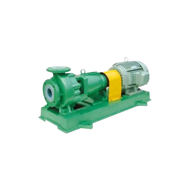
1. OverviewZA and ZAO petrochemical process pumps are designed according to AP1610 and VDMA24297 (light/medium duty) specifications. 2. Application sc...
See DetailsContent
An axial flow pump is a dynamic pumping device that moves fluid parallel to the pump shaft axis, utilizing a propeller-like impeller to impart velocity and pressure to the liquid. Unlike centrifugal pumps that discharge fluid radially outward from the impeller, axial flow pumps propel liquid in a straight axial direction through the impeller vanes, similar to how an airplane propeller moves air. This fundamental difference in flow path creates distinct performance characteristics that make axial flow pumps ideally suited for high-volume, low-head applications where large quantities of fluid must be moved against relatively modest pressure differentials.
The basic construction of an axial flow pump consists of a cylindrical casing housing a propeller-type impeller mounted on a shaft driven by an electric motor or other prime mover. The impeller typically features three to eight blades with airfoil-shaped cross-sections designed to efficiently convert rotational energy into fluid momentum. As the impeller rotates at speeds typically ranging from three hundred to eighteen hundred revolutions per minute, the vanes create a pressure differential that accelerates fluid axially through the pump. Guide vanes or diffuser blades positioned downstream of the impeller may be incorporated to recover velocity energy as static pressure, improving overall pump efficiency by converting kinetic energy into useful pressure head.
Axial flow pumps operate most efficiently when delivering high flow rates at low discharge heads, typically ranging from one to ten meters of head at capacities from several hundred to tens of thousands of cubic meters per hour. The performance curve of an axial flow pump exhibits a characteristic steep slope, with head decreasing sharply as flow increases beyond the design point. This contrasts with centrifugal pumps that display flatter curves and can operate across broader flow ranges without dramatic performance changes. The steep curve means that axial flow pumps are particularly sensitive to system resistance variations, with small changes in head requirements producing significant flow rate changes.
Specific speed, a dimensionless parameter characterizing pump hydraulics, ranges from approximately one hundred twenty to over three hundred for axial flow designs compared to twenty to one hundred for typical centrifugal pumps. This high specific speed reflects the pump's optimization for high flow and low head conditions. The relationship between impeller diameter, rotational speed, flow rate, and head is governed by affinity laws that predict how performance changes with speed variations. Variable speed operation through frequency drives provides effective flow control for axial flow pumps, allowing output adjustment to match varying demand while maintaining reasonable efficiency across the operating range.
Well-designed axial flow pumps achieve peak efficiencies between seventy-five and eighty-five percent when operating at their best efficiency point, comparable to or slightly lower than optimized centrifugal pumps. However, efficiency drops more precipitously when operating away from design conditions due to the specialized nature of axial flow hydraulics. Power consumption for axial flow pumps is calculated using the standard hydraulic formula incorporating flow rate, head, fluid density, and efficiency, with shaft power requirements ranging from several kilowatts for small units to megawatt levels for large flood control or water transfer installations.
The power characteristic curve for axial flow pumps typically shows decreasing power consumption as flow increases beyond shutoff conditions, contrasting with centrifugal pumps where power increases with flow. This means that axial flow pumps draw maximum power at shutoff or low flow conditions, requiring motors sized for this worst-case scenario even though normal operation occurs at higher flows and lower power. Non-overloading impeller designs can modify this characteristic to limit maximum power draw, preventing motor overload across the full operating range and allowing use of smaller, more economical motors.
| Application Sector | Typical Use Cases | Flow Range | Head Range |
| Flood Control | Drainage stations, stormwater | 5,000-50,000 m³/hr | 2-8 meters |
| Irrigation | Canal systems, field flooding | 1,000-20,000 m³/hr | 3-10 meters |
| Water Treatment | Circulation, aeration basins | 500-10,000 m³/hr | 1-5 meters |
| Power Generation | Cooling water circulation | 10,000-100,000 m³/hr | 3-12 meters |
| Marine Applications | Ballast, bilge, firefighting | 200-5,000 m³/hr | 5-15 meters |
| Industrial Process | Cooling loops, circulation | 300-8,000 m³/hr | 2-8 meters |
Despite their advantages for specific applications, axial flow pumps exhibit limitations that restrict their use to situations matching their performance envelope. The fundamental constraint is low head capability, with most axial flow pumps limited to discharge heads below fifteen meters and optimal performance occurring below ten meters. Applications requiring higher pressures necessitate centrifugal or mixed-flow pump designs. The steep performance curve characteristic of axial flow pumps creates operational challenges in systems with variable resistance, as small head changes produce large flow variations that may require throttling or variable speed control to maintain desired operating points.
Cavitation susceptibility represents another limitation, as the high flow velocities and low pressure regions around impeller blades create conditions favorable for cavitation if inadequate Net Positive Suction Head is available. Cavitation causes noise, vibration, erosion damage, and performance loss, requiring careful attention to suction conditions including minimizing suction line losses, providing adequate submergence, and potentially installing pumps in vertical configurations with impellers submerged below minimum water level. Axial flow pumps generally exhibit narrower high-efficiency operating ranges compared to centrifugal designs, with efficiency dropping substantially when operating significantly away from the best efficiency point, necessitating careful system design to ensure operation near optimal conditions.
Vertical wet pit or column-type installations represent the most common configuration for large axial flow pumps in municipal water, flood control, and irrigation applications. The pump impeller is mounted at the lower end of a vertical column extending down into a wet pit or sump, with the motor positioned above water level at grade or platform elevation. This arrangement allows the impeller to operate fully submerged, providing excellent NPSH conditions and eliminating priming requirements. The column pipe serves as both a structural support and discharge conduit, with bearings positioned along its length to support the shaft and maintain alignment. Elbow discharge configurations direct flow horizontally after vertical travel through the column, while straight vertical discharge maintains axial flow direction for installations feeding overhead channels or tanks.
Horizontal axial flow pumps position the shaft and impeller horizontally, typically in concrete volutes or pipe casings, with the drive motor located outside the wet pit connected through shaft extensions or right-angle gearboxes. This configuration suits applications with limited vertical clearance or where horizontal installation simplifies piping arrangements. Submersible axial flow pumps integrate a waterproof motor directly coupled to the impeller, with the entire assembly installed below water level. These units eliminate the need for dry pits, stuffing boxes, or complex sealing arrangements, reducing civil works and construction costs while providing compact, efficient pumping solutions for wet pit applications. Submersible designs particularly suit temporary installations, mobile pumping units, and applications where minimizing above-grade equipment is desired.
The first step in axial flow pump selection involves verifying that the application characteristics match the pump's performance envelope. Calculate required flow rate based on process needs, drainage requirements, or water transfer volumes, ensuring adequate margin for future capacity increases or peak demand scenarios. Determine total dynamic head including static elevation difference, friction losses in suction and discharge piping, minor losses through fittings and valves, and any pressure requirements at the discharge point. If calculated head exceeds approximately ten to twelve meters, mixed-flow or centrifugal pumps likely provide better solutions unless multiple axial flow pumps in series are considered.
Evaluate specific speed using the formula incorporating flow rate, head, and rotational speed to confirm that the application falls within the axial flow pump range typically above one hundred twenty. Consider whether the system exhibits relatively constant or widely varying resistance, as axial flow pumps suit stable systems better than applications with frequent, large head fluctuations. Assess solids content and characteristics including maximum particle size, concentration, and abrasiveness to ensure the pump can handle anticipated debris without excessive wear or clogging. Review available NPSH compared to pump requirements, recognizing that axial flow designs often demand higher NPSH than centrifugal alternatives due to higher suction velocities.
Once preliminary suitability is confirmed, detailed pump selection involves overlaying the system curve representing total dynamic head versus flow onto manufacturer performance curves to identify the operating point where system requirements intersect pump capability. The operating point should ideally fall within eighty-five to one hundred fifteen percent of the best efficiency point flow to ensure good efficiency and stable operation. Verify that the selected pump provides adequate head margin above minimum requirements to accommodate system variations, curve degradation over time, and potential increases in resistance from fouling or modifications.
Check NPSH available against NPSH required across the operating range, ensuring adequate margin of at least one meter to prevent cavitation under all anticipated conditions including temperature variations affecting vapor pressure. Review power requirements to confirm motor sizing adequacy, paying particular attention to shutoff or low-flow power consumption that may exceed normal operating values for standard axial flow designs. Evaluate whether variable speed operation provides benefits for controlling flow, improving efficiency at partial loads, or accommodating varying system conditions, weighing energy savings against additional cost and complexity of frequency drives.
Material selection for axial flow pump components depends on fluid characteristics, operating environment, and required service life. Impellers commonly utilize cast iron, ductile iron, or fabricated steel for freshwater applications, providing adequate strength and corrosion resistance at economical cost. Stainless steel impellers offer superior corrosion resistance for seawater, brackish water, or chemically aggressive fluids, though at higher cost. Bronze or specialized alloys may be specified for particular corrosive environments or where galvanic compatibility with other system components is required. Pump casings and columns typically employ cast iron, fabricated steel, or concrete depending on size, pressure rating, and installation type.
Protective coatings extend service life and reduce maintenance in corrosive or abrasive service, with options including epoxy coatings for general protection, polyurethane systems for enhanced abrasion resistance, or specialized coatings for chemical resistance. Cathodic protection systems prevent electrochemical corrosion in metallic pumps operating in conductive fluids, particularly important for seawater or wastewater applications. Sacrificial anodes or impressed current systems provide electrons that counteract corrosion currents, substantially extending equipment life in aggressive environments. Bearing materials must suit the operating environment with oil-lubricated antifriction bearings for dry installations, grease-packed bearings for outdoor or wet locations, or water-lubricated journal bearings for submersible applications.
Proper operation of axial flow pumps begins with ensuring adequate submergence and NPSH availability before startup to prevent cavitation damage. Verify that suction screens or trash racks are clear and that inlet conditions provide uniform flow distribution to the impeller without vortexing or air entrainment. Start pumps against closed or partially closed discharge valves for designs with rising power curves to prevent motor overload, then gradually open valves to achieve desired flow. Monitor operating parameters including flow rate, discharge pressure, power consumption, vibration levels, and bearing temperatures to verify normal operation and detect developing problems before failures occur.
Maintain operation near the best efficiency point whenever possible to maximize energy efficiency and minimize mechanical stresses that accelerate wear. Variable frequency drives enable efficient flow control by adjusting pump speed to match demand rather than throttling discharge valves that waste energy while maintaining high power consumption. Implement regular maintenance including lubrication of bearings, inspection of impeller and casing for wear or damage, verification of shaft alignment, and testing of protective systems including vibration monitors and temperature sensors. Monitor performance trends over time including increasing power consumption or decreasing flow at constant head that may indicate wear, fouling, or other degradation requiring corrective action.
Insufficient flow delivery from axial flow pumps can result from multiple causes requiring systematic diagnosis. Verify that actual system head matches design values, as unexpected increases in resistance from partially closed valves, fouled piping, or modifications reduce flow along the steep pump curve. Check for air leaks in suction piping that reduce effective pumping capacity and may cause erratic operation or complete loss of prime. Inspect impeller clearances and condition, as wear increases internal recirculation that reduces net flow delivery. Confirm correct rotation direction and verify that speed matches design specifications, as reduced speed dramatically decreases flow and head production according to affinity laws.
Excessive vibration indicates mechanical problems requiring prompt attention to prevent catastrophic failure. Common causes include misalignment between motor and pump shaft, worn or damaged bearings, impeller imbalance from erosion or debris accumulation, and resonance where operating speed coincides with natural frequencies of structural components. Cavitation produces characteristic noise and vibration along with erosion damage to impeller blades, necessitating investigation of suction conditions and NPSH adequacy. High power consumption relative to flow delivery suggests mechanical issues such as binding bearings, rubbing between rotating and stationary components, or operation far from best efficiency point where hydraulic losses consume excessive energy. Systematic evaluation of potential causes combined with performance trending and condition monitoring enables effective troubleshooting and corrective action before minor issues escalate to major failures requiring extended downtime and costly repairs.

1. OverviewZA and ZAO petrochemical process pumps are designed according to AP1610 and VDMA24297 (light/medium duty) specifications. 2. Application sc...
See Details
FSB fluoroplastic pump overview FSB-type fluoroplastic alloy pump is designed according to international standard dimensions. The pump body is organic...
See Details
AY type oil pump is divided into two structural forms: single-stage single-suction cantilever type, two-stage single-suction cantilever type, single-s...
See Details")
Performance Range: · Diameter: DN25~DN400 · Flow Rate: Up to 2000 m³/h · Head: Up to 200 m · Temperature Limit...
See Details
The Double Casing Slurry Pump, a series of solid-liquid two-phase flow slurry pumps, is engineered with an innovative two-phase flow design theory and...
See Details
The vortex pump is compact in size yet capable of generating high pressure, making it an ideal choice for achieving miniaturization of equipment. It e...
See Details
The Diversion-Type Long Shaft Submersible Desulfurization Pump is specifically engineered for underground sump applications in power plant flue gas de...
See Details
Our standard API 610 BB1 pumps are horizontally mounted, single-stage, double-suction units with an axially split casing between bearings. The pump an...
See Details
Based on the hydraulic platform of our OH3 pumps, these derivative models are offered in two compact configurations: rigidly coupled versions (OH4) mo...
See DetailsCopyright © Welcome to Chemical Pump Factory - Jiangsu Feixiang Pump Manufacturing All rights reserved. Chemical Pumps Manufacturers

